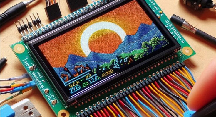
The 16×2 Liquid Crystal Display (LCD) is a popular choice for hobbyists and makers due to its affordability, ease of use, and versatility. If you’re venturing into the world of Arduino and want to learn how to control this handy display, this guide is for you! We’ll delve into the basics of the 16×2 LCD, explore connection methods, and guide you through writing simple Arduino code to check its functionality. Get ready to bring your projects to life with visual information!
Understanding the 16×2 LCD: A Display Breakdown
The 16×2 LCD boasts 16 columns and 2 rows, allowing you to display up to 32 characters at a time. These characters can be letters, numbers, or symbols. The display relies on a backlight for illumination, which can be controlled independently. While some models offer built-in contrast adjustment, others require an external potentiometer for fine-tuning the display’s clarity.
Connecting Your LCD to Arduino: Choosing the Right Path
There are two main ways to connect your 16×2 LCD to your Arduino board:
- 4-Bit Mode: This method utilizes only 4 of the 6 data pins on the LCD, requiring less Arduino pin usage but potentially needing slightly more complex code.
- 8-Bit Mode: This method utilizes all 6 data pins on the LCD, offering simpler code but requiring more Arduino pins.
Gathering Your Supplies: Essential Components
To embark on this exciting journey, you’ll need the following:
- Arduino Board: Choose a board that suits your project, such as the popular Arduino Uno.
- 16×2 LCD Display: Ensure you have the pin layout information for your specific LCD model.
- Jumper Wires: These will connect your Arduino to the LCD.
- Breadboard (Optional): This provides a convenient platform for prototyping your circuit.
- Resistor (Optional): Some LCD models require a contrast adjustment resistor (typically 10kΩ).
Wiring Up Your LCD: Bringing the Connection to Life
Here’s a breakdown of the wiring process for both 4-bit and 8-bit modes:
4-Bit Mode:
- Connect the LCD’s RS (Register Select) pin to an Arduino digital pin (e.g., pin 12).
- Connect the LCD’s E (Enable) pin to another Arduino digital pin (e.g., pin 11).
- Connect four of the LCD’s data pins (D4-D7) to four Arduino digital pins (e.g., pins 5-8).
- Connect the LCD’s VSS (Ground) pin to the Arduino’s GND pin.
- Connect the LCD’s VDD (Power) pin to the Arduino’s 5V pin.
- Connect the LCD’s contrast control pin (if present) to a 10kΩ resistor and then to the Arduino’s 5V pin (unless your LCD has a built-in contrast adjuster).
- Connect the other end of the resistor to the LCD’s VO (contrast control) pin.
- Backlight Connection (Optional):
- Connect the LCD’s backlight anode (positive) pin (if present) to the Arduino’s 5V pin.
- Connect the LCD’s backlight cathode (negative) pin (if present) to the Arduino’s GND pin through a 220Ω resistor.
8-Bit Mode:
- Connect the LCD’s RS, E, and all eight data pins (D0-D7) to eight separate Arduino digital pins.
- Follow the same steps for VSS, VDD, contrast control (if present), and backlight (if present) as in the 4-bit mode.
Introducing the LiquidCrystal Library: Simplifying Communication
The LiquidCrystal library simplifies communication between your Arduino and the LCD. Download and install this library through the Arduino IDE’s Library Manager. This library handles the low-level communication details, allowing you to focus on the data you want to display.
Writing Your First Arduino Sketch: Bringing the Display to Life
Here’s a basic Arduino sketch to check your LCD functionality in 4-bit mode (modify pin numbers if needed):
#include <LiquidCrystal.h>

const int rs = 12, en = 11, d4 = 5, d5 = 4, d6 = 3, d7 = 2;
LiquidCrystal lcd(rs, en, d4, d5, d6, d7);

void setup() {
  // Set the LCD size (columns, rows)
  lcd.begin(16, 2);

  // Clear the display
  lcd.clear();

  // Print a message to the display
  lcd.print("Hello, World!");

  // Set the cursor position (column, row)
  lcd.setCursor(0, 1);

  // Print the current time (seconds since reset)
  lcd.print(millis() / 1000);
}

void loop() {
  // No additional code needed in the loop for this basic example
}
Explanation of the Code:
- #include <LiquidCrystal.h>: This line includes the LiquidCrystal library, which provides functions for interacting with the LCD.
- Pin Definitions: These lines define the Arduino pins connected to the LCD’s RS, E, and data pins (modify these based on your wiring configuration).
- LiquidCrystal lcd: This line creates a LiquidCrystal object named “lcd” and initializes it with the pin connections.
- void setup(): This function runs once when the Arduino starts.
- lcd.begin(16, 2): This line initializes the LCD, specifying the number of columns (16) and rows (2).
- lcd.clear(): This line clears the LCD display.
- lcd.print(“Hello, World!”): This line prints the message “Hello, World!” on the first line of the display.
- lcd.setCursor(0, 1): This line sets the cursor position to the first column (0) of the second row (1).
- lcd.print(millis() / 1000): This line prints the current time in seconds (obtained from the
millis()function and divided by 1000) on the second line of the display. - void loop(): This function repeatedly runs after the
setup()function finishes. In this basic example, we leave it empty as no additional actions are needed.
Uploading the Code and Witnessing the Magic
- Connect your Arduino to your computer using a USB cable.
- Open the Arduino IDE software.
- Copy and paste the provided code into a new sketch.
- Select your Arduino board type and serial port from the respective menus in the IDE.
- Click the upload button (usually an arrow pointing upwards) to upload the code to your Arduino board.
- If everything is connected correctly, you should see the message “Hello, World!” on the first line of your LCD and the current time in seconds updating on the second line.
Troubleshooting Tips: No Display? Don’t Fret!
If you encounter issues, here are some troubleshooting steps:
- Double-check your wiring: Ensure all connections between the LCD and Arduino are correct based on your chosen mode (4-bit or 8-bit).
- Verify the code: Make sure there are no typos or errors in the uploaded code.
- Confirm library installation: Ensure the LiquidCrystal library is properly installed in your Arduino IDE.
- Adjust contrast (if applicable): If your LCD has a contrast control potentiometer, try adjusting it for better visibility.
Beyond the Basics: Exploring Advanced Functionality
The provided code offers a basic example, but the LiquidCrystal library unlocks a wider range of functionalities:
- Clearing Specific Lines: Use
lcd.clear()to clear the entire display orlcd.setCursor(0, 0); lcd.print(" ");to clear a specific line. - Cursor Control: Use
lcd.setCursor(column, row)to position the cursor for precise text placement. - Scrolling Text: For longer messages, enable scrolling using
lcd.scrollDisplayLeft()orlcd.scrollDisplayRight(). - Custom Characters: Define custom characters for symbols or icons using
lcd.createChar().
Conclusion
By following this guide, you’ve gained the knowledge and practical skills to check your 16×2 LCD display with Arduino. From understanding the connection methods to writing basic code and troubleshooting common issues, you’re well on your way to incorporating visual elements into your Arduino projects.
The provided code serves as a springboard for further exploration. The LiquidCrystal library offers a wealth of functions for displaying text, symbols, and even custom characters, allowing you to customize your projects and unleash your creativity.
So, feel empowered to experiment, explore advanced functionalities, and bring your ideas to life with the power of the 16×2 LCD and Arduino! Remember, the journey of learning is continuous. As you delve deeper into electronics and programming, you’ll discover new possibilities and unlock the full potential of this versatile display in your Arduino projects.


